C4 Component Diagram Best Practices: Examples & Templates (2026)
C4 Component Diagram Best Practices: Design Patterns & Guidelines
Component diagrams represent the third level of the C4 model, showing the major structural building blocks within a container and their interactions. Getting component diagrams right is crucial for communicating complex internal architectures and guiding implementation decisions.
What Are C4 Component Diagrams?
Component diagrams zoom into a specific container to show:
- Major classes or components and their responsibilities
- Interfaces between components
- External dependencies and integrations
- Internal structure and organization patterns
Component diagrams bridge the gap between high-level container architecture and low-level code implementation, making them invaluable for development teams.
Best Practices for Component Design
1. Focus on Significant Components Only
Don't include every class - Component diagrams should show major structural elements, not every implementation detail.
Good component candidates:
- Controllers and API handlers
- Business logic services
- Data access layers
- Integration adapters
- Core domain models
Avoid showing:
- Utility classes and helpers
- Simple data transfer objects
- Configuration classes
- Minor implementation details
2. Show Clear Interfaces and Dependencies
Make component interactions explicit:
[User Controller] --> [User Service] --> [User Repository]
                                     --> [Email Service]
[User Repository] --> [Database]
[Email Service] --> [SMTP Provider]
Interface guidelines:
- Use consistent naming for similar interfaces
- Show direction of dependencies with arrows
- Group related components visually
- Highlight external dependencies clearly
3. Apply Consistent Naming Conventions
Use descriptive, consistent names:
- Controllers:
UserController,OrderController - Services:
PaymentService,NotificationService - Repositories:
UserRepository,ProductRepository - Adapters:
PaymentProviderAdapter,EmailAdapter
Avoid generic names:
Manager,Handler,Processor(unless specifically meaningful)Utils,Helper,Common- Technical implementation details in names
Common Component Patterns
Layered Architecture Pattern
[Presentation Layer]
    [User Controller]
    [Order Controller]

[Business Logic Layer]
    [User Service]
    [Order Service]
    [Payment Service]

[Data Access Layer]
    [User Repository]
    [Order Repository]
    [Payment Gateway]
Benefits:
- Clear separation of concerns
- Testable business logic
- Consistent structure across teams
Hexagonal Architecture (Ports & Adapters)
[Core Domain]
    [User Service] <-- [User Port]
    [Order Service] <-- [Order Port]

[Adapters]
    [REST Controller] --> [User Port]
    [Database Repository] --> [User Port]
    [Message Queue] --> [Order Port]
Benefits:
- Domain-driven design alignment
- Easy testing with mock adapters
- Technology-agnostic core logic
Event-Driven Components
[Event Publisher] --> [Event Bus] --> [Event Handler A]
                                  --> [Event Handler B]
                                  --> [Event Handler C]
Key elements:
- Clear event schemas and contracts
- Decoupled component interactions
- Asynchronous processing capabilities
Component Diagram Guidelines
1. Appropriate Level of Detail
Too much detail:
- Showing every method and property
- Including framework-specific components
- Displaying temporary or utility objects
Right level of detail:
- Key business components and their roles
- Important interfaces and contracts
- External system integrations
- Critical data flow patterns
2. Visual Organization
Group related components:
- Use containers or background colors for layers
- Position related components near each other
- Show clear boundaries between concerns
Consistent styling:
- Same shapes for similar component types
- Consistent colors for different layers
- Clear visual hierarchy
3. Documentation Integration
Link your component diagrams to:
- Architecture Decision Records explaining design choices
- Code documentation and API specifications
- Implementation guidelines and standards
Microservices Component Examples
For a microservices architecture, component diagrams typically focus on a single service:
User Service Components
[User API Controller]
    --> [User Command Service]
    --> [User Query Service]

[User Command Service] --> [User Repository]
                       --> [Event Publisher]

[User Query Service] --> [Read Model Repository]

[User Repository] --> [PostgreSQL Database]
[Read Model Repository] --> [Redis Cache]
[Event Publisher] --> [Message Queue]
This shows:
- CQRS pattern implementation
- Clear separation between commands and queries
- Event-driven architecture integration
- Multiple data storage strategies
Order Processing Components
[Order Controller] --> [Order Service]
[Order Service] --> [Order Repository]
               --> [Payment Client]
               --> [Inventory Client]
               --> [Notification Service]

[Payment Client] --> [Payment Service API]
[Inventory Client] --> [Inventory Service API]
[Notification Service] --> [Email Provider]
Key patterns shown:
- Service composition pattern
- External service integration
- Cross-cutting concerns (notifications)
Integration with Other C4 Levels
Component diagrams work best when integrated with the complete C4 model:
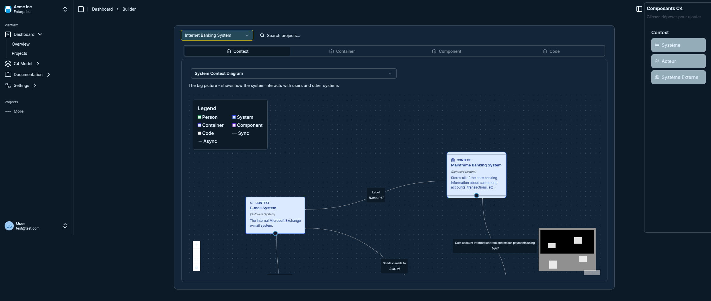
- Start with context: Use C4 context diagrams to establish system boundaries
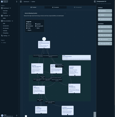
- Define containers: Create container diagrams to show high-level architecture
- Detail components: Use component diagrams for complex containers
- Link to code: Connect components to actual implementation
For teams new to C4, our complete tutorial provides step-by-step guidance on using all four levels effectively.
Tools and Templates
Our C4 visualization tool provides:
- Component diagram templates for common patterns
- Pre-built components for popular frameworks
- Automatic layout suggestions for complex diagrams
- Integration with documentation systems
Common Mistakes to Avoid
1. Too Much Implementation Detail
❌ Avoid: Showing every class, method, and property ✅ Do: Focus on significant components and their interactions
2. Inconsistent Abstraction Levels
❌ Avoid: Mixing high-level services with low-level utilities ✅ Do: Keep all components at similar abstraction levels
3. Missing External Dependencies
❌ Avoid: Only showing internal components ✅ Do: Clearly show external systems and APIs
4. Outdated Diagrams
❌ Avoid: Creating static diagrams that never get updated ✅ Do: Keep diagrams current with code changes
Advanced Component Patterns
Domain-Driven Design Components
[User Aggregate Root]
    [User Entity]
    [User Value Objects]

[User Domain Service] --> [User Aggregate Root]
[User Application Service] --> [User Domain Service]
[User Repository Interface] <-- [User Domain Service]

[User Infrastructure]
    [User Repository Impl] --> [Database]
    [User API Controller] --> [User Application Service]
Clean Architecture Components
[Entities Layer]
    [User Entity]
    [Order Entity]

[Use Cases Layer]
    [Create User Use Case] --> [User Entity]
    [Process Order Use Case] --> [Order Entity]

[Interface Adapters]
    [User Controller] --> [Create User Use Case]
    [Database Gateway] --> [User Repository Interface]
Conclusion
Effective component diagrams require balancing detail with clarity, showing enough information to guide implementation while remaining understandable to stakeholders. By following these best practices and patterns, your component diagrams will serve as valuable documentation that evolves with your codebase.
Remember that component diagrams are most effective when they're part of a complete C4 model documentation strategy, providing the detailed view that complements higher-level system architecture diagrams.